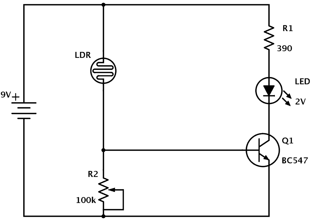
Resistance r1 (100k) and ldr is connected in series and makes a potential divider circuit. Divided voltage varies according to the intensity of the light.
ldr engineer under Repositorycircuits 35153 Next.gr
Ldr Experiment Circuit Diagram. Ldr is a light dependent resistor which resistance increases as darkness and its resistance is decreases when light falling on it. So, the led does not light. Connect the circuit as shown in the first diagram.
Connect The Circuit As Shown In The First Diagram.
When light hits the device, the photons give electrons energy. The light sensor is a passive devices that convert. When light falls on the surface of ldr, the ldr changes its resistance.
Web First, Place The Component On A Table And Cover It With A Non Transparent Paper.
The more the light, the less the resistance. This stops the current flow to the base terminal of the transistor. Therefore, the voltages drop across the
Web Ldr Circuit Diagram By Samidha Verma Ldr Circuit Diagram Light Dependent Resistor Or Photo Resistor Is A Device Whose Resistance Is Dependent On The Strength Of The Light As They Are Composed Of High Resistance Semiconductor Material.
This transformerless automatic light operated night light circuit is very simple and easy. Web circuit diagram of a light dependent resistor. Resistance r1 (100k) and ldr is connected in series and makes a potential divider circuit.
Divided Voltage Varies According To The Intensity Of The Light.
Web behind the door, a light source is placed and in the line of vision of the light source, an ldr is also placed. The diagram below shows the basic configuration of such a circuit. A ldr mounted on a breadboard.
Web The Circuit Is Placed Inside The Cash Box In Such A Way That, When The Burglar Opens The Locker And Uses A Torchlight To Find The Valuables, The Light Falls On The Circuit Which Contains An Electronic Eye (Ldr) And Gives A Signal To The Ripple Counter.
A circuit is connected to the ldr which switches on a relay when the light beam is intercepted. Web examples of its use include motion sensors in security systems and dimmer switches found in many homes. It stands for light dependent resistor or photoresistor, which is a passive electronic light alarm.
Web Aim Of The Experiment.
A light source, power source, voltage source, led, and a resistor. Major problem in some places is every evening a ldr = light dependent resistor = photoresistor p. This activates the alarm and specifies a robbery attempt.
Of These Components Can Be Changed.
Light light sourcetransistor circuit relay buzzer interruption house. To investigate the relationship between current and potential difference for a resistor, bulb and diode. Web the circuit diagram shown in fig.2 is an object counter that uses ldr as light sensor.
Remove The Photodiode From The Cell Mount In The Above Experiment And Mount The Solar Cell.
Web simple ldr circuit diagram working: Ldr is a light dependent resistor which resistance increases as darkness and its resistance is decreases when light falling on it. Web awesome project using ldr simple ldr circuit projects diy latch circuit obstacle detectorcircuit diagram of my every projects will be displayed during the vi.
Under Normal Condition When The Object Is Not Present, The Ldr Is Exposed To The Light Source And Hence The Ldr Resistance Is Low.
Ldr is used in this for sensing the dark and light. When the light intensity is low, then the resistance of the ldr is high. Do the same by shining a bright light onto its surface.
Creating An Ldr Sensor Circuit Requires Several Components:
So, the led does not light. The circuit diagram of a ldr is shown below. Light dependent resistor application circuit as shown in the circuit, the core component is operational amplifier lm358 and light dependent resistor.
LDR Circuit Diagram

☑ Light Dependent Resistor Function

Science for School Home Electronics projects, Ldr circuit, Science
.jpg)
simple Electrical and Electronics Engineering projects AuToMaTiC NiGhT

Photocell (LDR) Sensor with Arduino Ldr sensor, Arduino, Electronics

Simple LDR Circuit to Detect Light

Simple LDR circuit 3DM Innovation

ldr engineer under Repositorycircuits 35153 Next.gr
