Web more nonlinearity to the output of the bridge circuit. As a common and simple method, the calibration models.
Principle diagram of linearization using analog predistortion circuit
Linearization Circuit Diagram. Web the proposed scheme consists of a single 2bit flash type adc, a (4 × 1) multiplexer (mux) and four linearization circuits. The two coils at centre are mechanically connected, and are energized. The view is perpendicular to the channel axis.
The Idea Itself Is Quite Simple, But The Implications Have Great Meaning For Our.
The work in [12] presents a linear digital cmos. Ask question asked 1 year, 6 months ago modified 1 year, 6 months ago viewed 115 times 0 i've created a circuit in ltspice. Web briefly described, and in accordance with one embodiment thereof, the invention provides a linearization circuit including a sensor circuit having a first.
Web Linear Circuit Elements Refer To The Components In An Electrical Circuit That Exhibit A Linear Relationship Between The Current Input And The Voltage Output.
The view is perpendicular to the channel axis. Web more nonlinearity to the output of the bridge circuit. Web introduction linearity is a mathematical concept that has a profound impact on electronic design.
Therefore, To Simplify The Design And Calibration Of A Sensor, A Linear Relationship Between Input And Output Is Highly Desirable.
Web how do you interpret ltspice graphs? Web linearize an electronic circuit. The scheme can divide entire.
Web That Is, A Linear Circuit Is A Circuit In Which (1) The Output When A Sum Of Two Signals Is Applied Is Equal To The Sum Of The Outputs When The Two Signals Are Applied Separately,.
As a common and simple method, the calibration models. Web in the study of dynamical systems, linearization is a method for assessing the local stability of an equilibrium point of a system of nonlinear differential equations or discrete. For an ideal signal processing, a linear straight line between output signal and measurand is preferred.
Linear Induction Motor Is A Special.
One direct and powerful method for the analysis of nonlinear systems involves approximation of the actual system by a linear one. The two coils at centre are mechanically connected, and are energized. Web explanation [ edit] linearity refers to the ability of the amplifier to produce signals that are accurate copies of the input, generally at increased power levels.
Web The Proposed Scheme Consists Of A Single 2Bit Flash Type Adc, A (4 × 1) Multiplexer (Mux) And Four Linearization Circuits.

Principle diagram of linearization using analog predistortion circuit

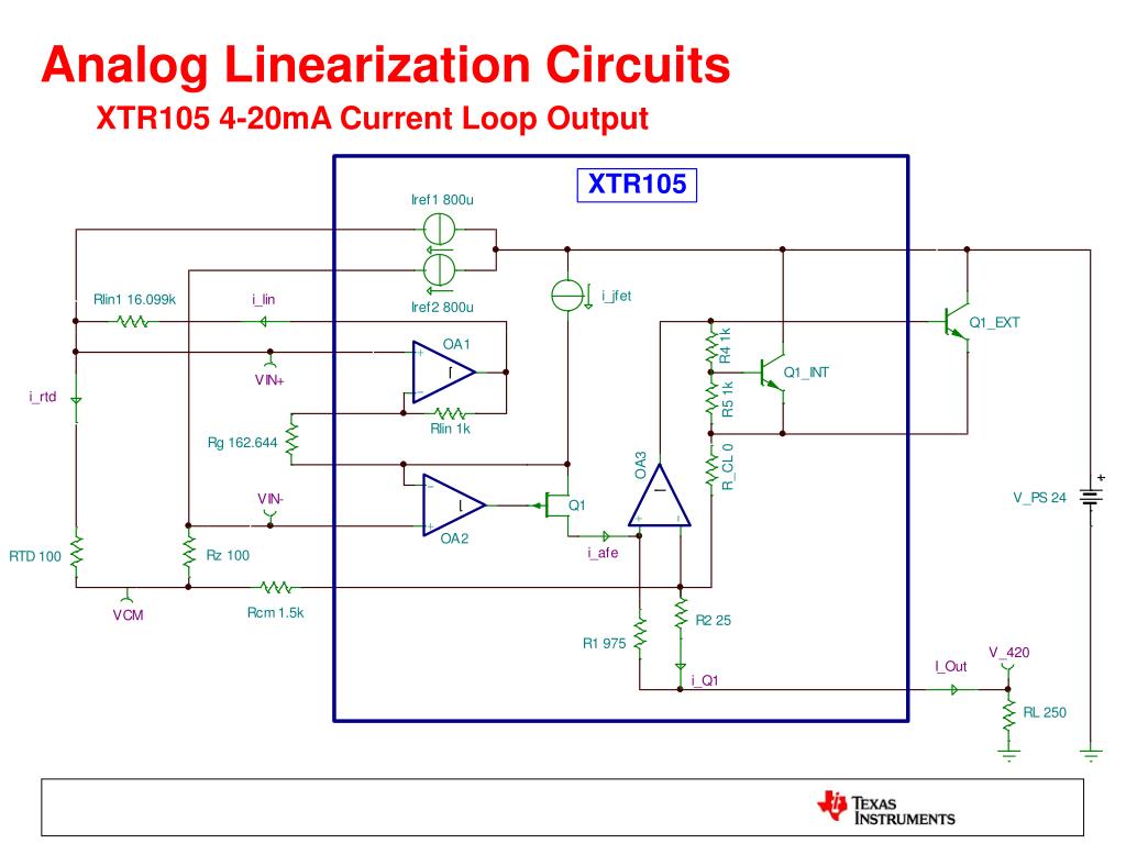
PPT Signal Conditioning and Linearization of RTD Sensors PowerPoint

PPT 4.4 Linearization and Differentials PowerPoint Presentation, free

PPT Signal Conditioning and Linearization of RTD Sensors PowerPoint

Wheatstone Bridge Measurement Circuit

PPT Signal Conditioning and Linearization of RTD Sensors PowerPoint

PPT Signal Conditioning and Linearization of RTD Sensors PowerPoint

Analog Design TradeOffs in Applying Linearization Techniques Using
