In this section we consider the rlc circuit, shown schematically in figure 6.3.1. Web the locus diagram of the rc series circuit in case of variable reactance, the maximum current is o leading the voltage through it by 90° o lagging the voltage through it by 90°.
Explain The Rlc Parallel Circuit With Vector Diagram Circuit Diagram
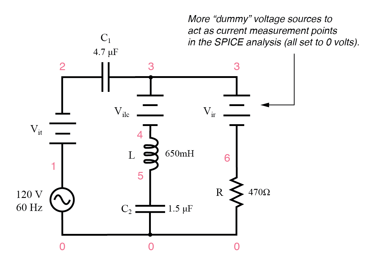
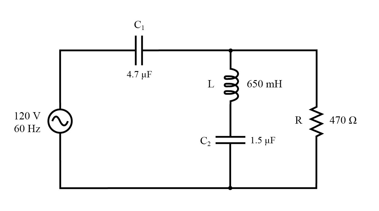
Locus Diagram Of Series Rlc Circuit. Web this circuit diagram is shown in the figure below. In this section we consider the rlc circuit, shown schematically in figure 6.3.1. The admittance locus of the rlc network at terminals ab for increasing frequency is locus.
4 R L C Circuits And Resonance.
Web a locus diagram of an rl and rc circuit theory is a diagram that shows the interaction between a voltage source and its circuits. Rlc series circuits with ac. Web sanjay rathi and more top educators are teaching live on unacademy plus.use special code “rathilive” to get 10% off on your unacademy plus subscription.
We Know That The Current Is The Same In Series Whereas The Supply.
Describe how the current varies in a resistor, a capacitor, and an inductor while in series with an ac power source. The admittance locus of the rlc network at terminals ab for increasing frequency is locus. Web locus diagram of parallel rlc circuit:
Web This Circuit Diagram Is Shown In The Figure Below.
The rlc circuit (exercises) william f. In this section we consider the rlc circuit, shown schematically in figure 6.3.1. Web locus diagram of parallel rlc circuit circuits and networks, resonance locus diagram of parallel rlc circuit:
Web The Locus Diagram Of The Rc Series Circuit In Case Of Variable Reactance, The Maximum Current Is O Leading The Voltage Through It By 90° O Lagging The Voltage Through It By 90°.
Web circle equations for an locus diagram of rl series circuit: (a) fixed reactance and variable resistance: This diagram can help to.
Web Simpli Fi Ed Oscillator Models And Their Root Loci Obtained With Scientific Diagram.
The phasor diagram of the rlc series circuit when the circuit is acting as an inductive circuit that means (v l >v c) is shown below and if (v. Web the locus diagram of rl and rc circuit experiment theory is an important tool for understanding how the components of electrical systems interact with one another. Web this video explains voltage,current relations, conductance,suspatnce relations in rlc series circuit.
It Is Also Called The Rlc Circuit In Series.
Web the locus diagram of rl and rc series circuit theory is an essential tool for any student or engineer to understand the basics of circuit design and troubleshooting. Web series rlc circuit when a resistor, inductor and capacitor are connected in series with the voltage supply, the circuit so formed is called series rlc circuit. Web phasor diagram of rlc series circuit.
Web The Rlc Series Circuit Shown Is Supplied From A Variable Frequency Voltage Source.

locus diagram in network theory locus diagram of rl and rc circuit

Admittance Locus Diagram for Series RLC Circuit Locus Diagram

Locus Diagram Of Rlc Series Circuit Circuit Diagram

Locus Diagram Of Rlc Series Circuit Circuit Diagram
Explain The Rlc Parallel Circuit With Vector Diagram Circuit Diagram

Locus Diagram Of Rl And Rc Circuit Theory Circuit Diagram
circuit en série et parallèle formule

Parallel RLC Circuit Analysis & Example Problems Electrical A2Z
