Web ladder diagrams help us to formulate the logic expressions in graphical form. There are all sorts of standards for serial signaling.
PLC program example with toggle or flipflop function Ladder logic
Logic Level Circuit Wiring Diagram. Web the 0 and 1 numbers are logic levels (0 = logic 0, 1 = logic 1), which are created by voltages in a circuit: Web when driving a logic low output, the voltage could be as high as volmax. Web ladder diagrams help us to formulate the logic expressions in graphical form.
Three Phase Logic 5.0 Diagram.
Serial communication at a ttl level will always remain. We'll go over all of the fundamental schematic symbols: Thus, an industrial electrician or electrical engineer.
Electrical Circuits Can Be Categorized Into A Number Of Different Types With All Of Them Having Applications They.
To download the diagrams, click the links below. Then we'll talk about how those symbols are connected. There are all sorts of standards for serial signaling.
Web The Diagram In This Article Shows How A Sequential Circuit Involves Both A Combinational Circuit (What We've Learned Here) And Memory Elements:.
A digital input will have a datasheet specification for its vihmin and vilmax. • in positive logic, 0 is formed by a low voltage level, and 1 is. Web logic 5.0 wiring diagram.
Web When Driving A Logic Low Output, The Voltage Could Be As High As Volmax.
Web in an effort to make plcs easy to program, their programming language was designed to resemble ladder logic diagrams. As shown in the event tree logic diagram in figure 31.4, in the. Web draw logic circuit online is an excellent tool for creating professional level wiring diagrams.
Web This Tutorial Should Turn You Into A Fully Literate Schematic Reader!
Web the wired or connection electrically performs the boolean logic operation of an or gate using open emitter or similar inputs (which can be identified by the ⎏ symbol in. Web how do you draw a logic circuit diagram? Let's look at a couple of the more popular hardware implementations of serial:
Web Ladder Diagrams Help Us To Formulate The Logic Expressions In Graphical Form.
Logic families such as ttl can sink more current than they can. Single phase logic 5.0 diagram. Web logic diagrams have several applications in investigations, and are most often developed in an iterative fashion.
Web The 0 And 1 Numbers Are Logic Levels (0 = Logic 0, 1 = Logic 1), Which Are Created By Voltages In A Circuit:
Web in a variety of ways, actually.

switches Logic level switch controlled via ground (0v) Electrical

microcontroller 3.3V to 5V logic level shifter with 3.3V

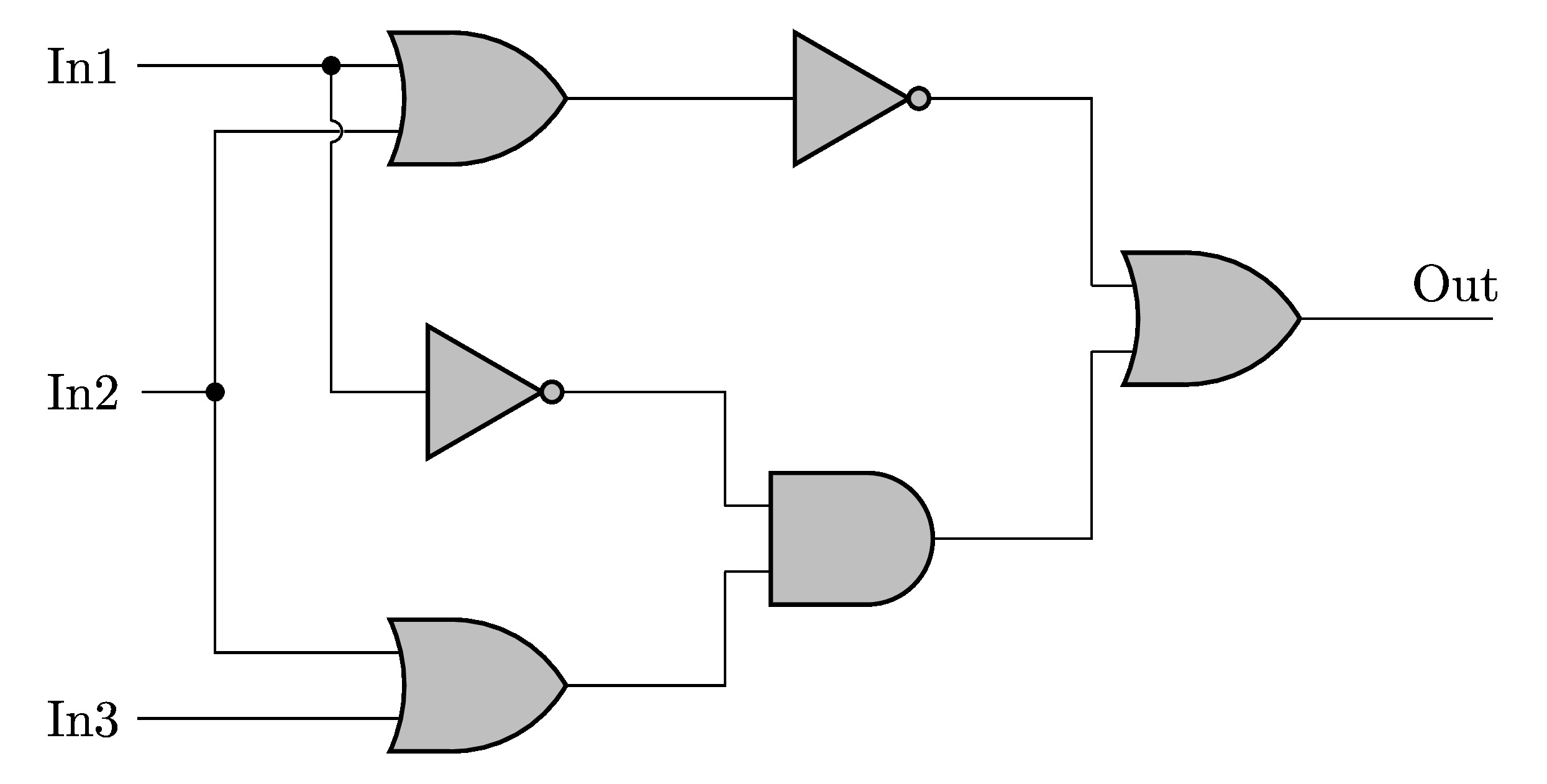
Xor Gate Logic Diagram / Xor Gate Logic Diagram Wiring Diagram

PLC program example with toggle or flipflop function Ladder logic

Example of motors with cooling in ladder logic Ladder logic, Plc
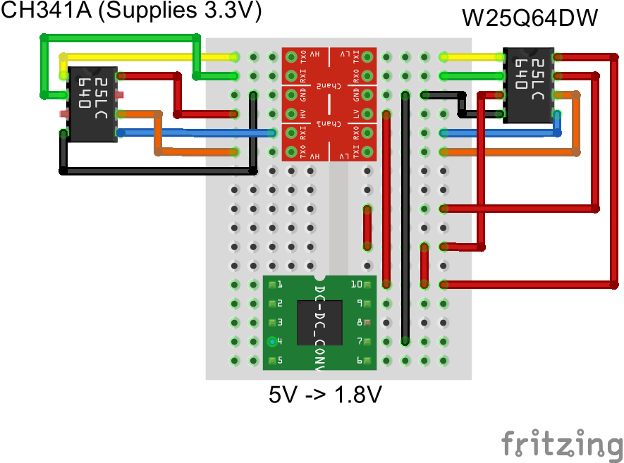
programming Wiring for Logic Level Converter to 1.8V SPI Flash with a

Logic Level Shifter, 4Channel, Bidirectional
Draw a Logic Circuit in CircuiTikZ TikZBlog
